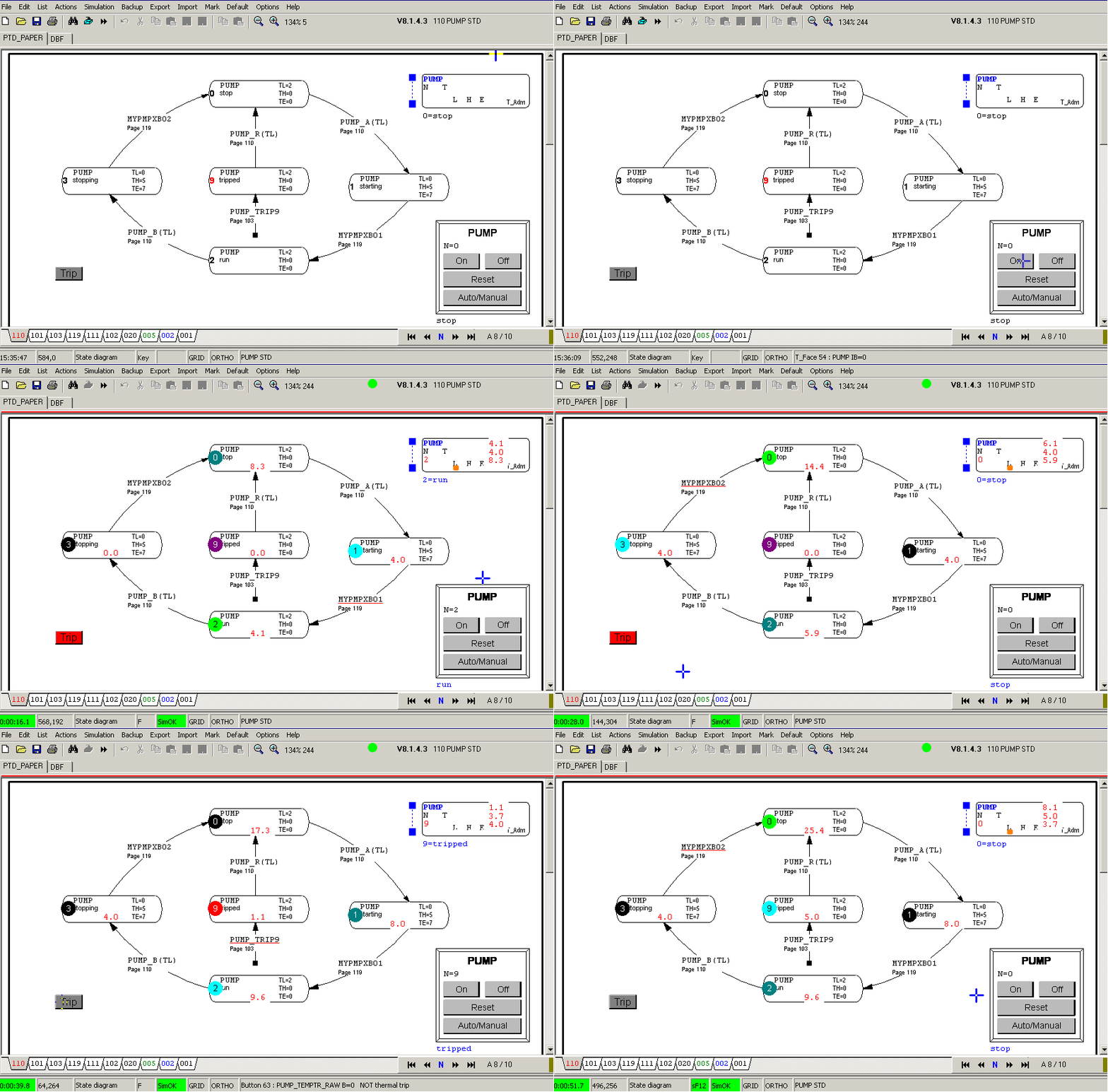
PTD pump example drawing 4
Notice how the project is compiled and simulated:

The first test is to press the "On" button on the faceplate. Notice the colored trace in the STD and the timing values. Each state is showing the cumulative active time: very convenient for proving that it has been active once. The actual times are shown at the T_Adm symbol.
The second time that PUMP2 is active, I press the Trip button. Notice how PUMP9 is active and how the colored trace is informing you were it happened.
The reset command is needed to continue. First test was succesfull.
Some remarks about the animation.
- After starting HCSimul, HCADwin failed to enter the animation mode. It happens rarely, or I clicked on the red line above the logic indicating that animation is active. Clicking here activated normal drawing. Clicking the start simulation icon will set HCADwin in animation mode if HCSimul was running.
For that reason you see the simulation timer (bottom left in green) starting from 5.9 seconds, not 0.1. - The real live example of inverting the RAW input on page 101, is showing a disadvantage now:bthe TRIP botton is showing the True in red, but its meaning was "NOT thermal trip". I like "what you see is what you get", so I have to live with the red color in the normal position here. Of course the operator interface should not present that. But a normal trip command from screen will be a normal button.
For simulation purposes I like to stay close to the real world. Simulate all aspects and not partially manipulated.


