Cadres for each page type
Advanced HCADwin users will have the need of changing the cadre (=border).
Since version V4.1 the changing of the border is made much easier by using the K command. The current cadre definition file for the actual page can be edited on screen as if it was logic. Just delete/change/insert symbols. For bitmaps (.BMP) or metafiles (.WMF) keep in mind that the bitmap or metafile must reside in the project or template directory. Using a C or F8 or <Ctrl>F8 command on the bitmaps can be used to alter its size (Grid/Ortho in the Off position). When using the K command, all expressions and includes are evaluated. When leaving the Border mode with another K command, only simple coordinates will be left.
Note that since V5.3.1.7 the Landscape A3 format is changed! It used to be 140x198 grid positions, but is enlarged to 140x206. It is possible to return to the old size, add and alter this line in the CNF:
POR_A4=125x80;LAN_A4=57x80;LAN_A3=140x206;POR_A3=184x120
When using the "Edit" function: Please read the remarks in the lesson about the CNF configuration again. The instruction KADER=HCWINKAD is were the definition of the cadres in HCADwin starts. Suppose you will change the instruction into KADER=CADRE. You'll have to provide the 6 different cadre definitions which HCADwin could use:
- Normal Portrait pages: CADRE.HKP
- Landscape pages: CADRE.HKL
- Control logic (landscape A3 with a higher resolution) pages: CADRE.HKR
- First or deviating (Special, like a frontpage) page: CADRE.HKV
- NenCompact pages (also portrait, but different symbol layout): CADRE.HKN
- NenCompact large pages (landscape A3, but different symbol layout): CADRE.HKM
- Portrait A3, for Hookups: CADRE.HKH
These ASCII files are expected in the project directory, or in the HCADwin template directory. In this lesson it will be sufficient to deal with the HKP file only, because that's all we are using now.
We will do the following exercise: copy with windows explorer the HCWINKAD.HK* files into your project directory (..\COURSE) and rename them into CADRE.HK*. By doing this you have created your own cadre definition specially for this project. Don't forget to change the KADER=CADRE instruction in the CNF.
After doing this, you'll have to save and open the COURSE project. HCADwinreads cadre information into memory when opening a project.
As mentioned in the CNF configuration lesson you can create as much keywords as you like. Keywords must not have strange characters or spaces, please restrict yourself to uppercase normal (A..Z) characters and use the "=" sign without spaces.
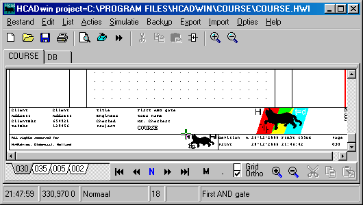
Try "Edit, Cadres, Portrait Cadre" and you start the built in editor of HCADwin showing:
B,456,920,573,967,nem.wmf
B,577,934,629,960,hcadlogo.bmp
T,-8,993,90,{3N4}%PAD
L,0,0,0,1000,3,0,0
L,0,0,640,0,3,0,0
L,0,920,640,920,3,0,0
L,0,970,640,970,1,0,0
L,0,1000,640,1000,3,0,0
T,5,922,0,{2N6}Client|Klant
T,5,932,0,{2N6}Address|Adres
T,5,942,0,{2N6}ClientNbr|Klant.Nr
T,5,952,0,{2N6}TekNbr|Tek.Nr
T,5,975,0,{2N5}All rights reserved for|Alle rechten blijven voorbehouden aan
T,5,987,0,{2B5}HvHAdvies, Oldenzaal, Holland
T,82,922,0,{2N7}@KLANT
T,82,932,0,{2N7}@KLANTADRES
T,82,942,0,{2N7}@KLANTNR
T,82,952,0,{2N7}@TEKNR
T,163,950,0,{2N6}Checked|Gecontroleerd
T,164,922,0,{2N6}Title|Titel
T,164,940,0,{2N6}Engineer
T,164,959,0,{2N6}Project
T,241,922,0,{2N7}%TITEL
T,241,931,0,{0N7}%TITEL2
T,241,940,0,{2N7}%ENGINEER
T,241,949,0,{2N7}@CHECKED
T,241,988,0,{2B8}%KKS
T,242,957,0,{2B9}@PROJECT
L,390,970,390,1000,1,0,0
T,392,973,0,{2N7}Revision|Revisie
T,392,986,0,{2N7}Print
T,444,973,0,{0N7}%REV
T,455,985,0,{2N7}%DATUM
T,605,973,0,{2N7}Page|Blad
T,605,986,0,{2B7}%BLZ
T,639,928,270,{3I5}%LVERSIE
L,640,0,640,1000,3,0,0
Add the instruction T,0,0,0,@EXTRA as an extra line and look at the upper left corner of any page in your project now.
Change it into T,0,300,0,Plain text and look again.
Change it into T,0,300,0,@EXTRA and look again. Try T,0,300,90,@EXTRA too and again look.
Now add the keyword EXTRA=Lot's of fun in the CNF. See what happens.
And add T,W-1,100,270,%PAD in the HKP. Look on the right side of your HCADwin page.
Add L,W-12,100,W-12,H,2,0,1 in the HKP and look again.
Normally the K command should be used in conjunction with the normal drawing instructions. The above example is used to give a better understanding.
Let me explain what you did. First of all the three instructions in the HKP were generating the cadre as you could see.
- The B,577,934,629,960,hcadlogo.bmp instruction puts the BMP (bitmap file, no more than 256 colors) on the correct position.
Read the line as follows: Bitmap at (X1,Y1) X2,Y2) from file BMP. Here too the file is searched in the project directory and if not found in the template directory. The X1,Y1 coordinates can be found by putting the HCADwin cursor on the top left corner of the bitmap on the page.

Look at the green HCADwin cursor just on the top left position of the black cat. On the status bar, next right to the clock, you see on the left side 330,970 0. Forget the last zero (it indicates the drawing mode) and X1=330; Y1=970 will be read. Knowing that a portrait page has a width of 640 (W=640) and the normal drawing area has a Height H=920 (or use G=1000 for the page height in total) you see that HCADwin can even calculate simple expressions for those parameters. - The T,0,300,90,@EXTRA is easy to read: Place a Text on (0,300) with a rotation of 90 degrees. The text itself must be substituted (@) from EXTRA of the CNF. The %PAD (shows the project filename and path) is an additional keyword, but now not from the CNF, which you could add or alter as we did before, but from some system keywords. Try %ENGINEER, %TITEL (Title), %REV(highest revision), %RD1 (first revision date), %RT1 (first revision text), %REV1 (first revision), %BLZ (this page), %NBLZ (next page), %NBR (number of pages), %VERSIE (short HCADwin version), %LVERSIE (long HCADwin version)
- The L,W-12,100,W-12,H,2,0,1 is used to draw a Line from (X1,Y1) to (X2,Y2) while Width=2, line type=Normal (1=dotted), and color=1 (Red)
Color numbers can be found when Changing (C command) an Slyn. All 16 HCADwin colors are shown, the number will appear when the cursor points to a color.
As an extra exercise do the following: Somewhere in your firm must be a WORD document with the logo of your company. Open it and be sure it can be seen on the screen completely. The use the <Alt><Print Screen> keys. Start Paint and give a Paste command. Select that part of the screen where the logo resides. And give the Copy (or Cut) command. Now create a new image in Paint by the "New" command. (Throw away what you saw) Make sure this new, white, picture is very small. Now again the Paste command. You should see now only the logo you want. Give the "Save As" command and be sure that no more than 256 colors are selected. Name it :MyLogo.BMP and place it directly into the COURSE project directory. Remember the size of the logo, because its aspect ratio is important. Now alter one of the B,x1,y1,x2,y2,bitmap instructions by using MyLogo.BMP or MyLogo.WMF. Maybe you have to adjust the coordinates in order to get a proper picture. (HCADwin stretches the picture into the given coordinates. Giving F8 when using the BMP symbol will alter the symbol size to the original BMP or WMF size).
What we have learned:
- Everything you see on the screen and in the printout, can be adjusted.
- A project will read cadre configuration files (name in the CNF) with drawing commands in ASCII.
- Two different substitution mechanisms are provided (@ and % as first token)
- Insert your own logo by creating a BMP or WMF and use that file.
- The search path of BMP's, WMF's or HKP's is always:
1. own directory;
2. Template directory
3. HCADwin directory. - Cadres can be made in ACAD (1996 thru 1999, now use the K command for direct drawing). Just export to DXF and HCADwin does the rest. (Creating the HUP, which can be included in the HKP)
- HCADwin has an in built simple expression evaluator.


