PTD pump example drawing 4
First I made the following adjustments:
- Visit page 119 and perform a C command on the OCvlv symbol.
Now the R column in the DBF is created and filled with "6", the type parameter.
It allows the SymA symbol to reflect the same shape. - Visit page 103 and perform a C command on the FFail symbol.
Now the FFAIL table is created and filled after the popup menu command "FirstFail table". - Visit the DBF and complete the SERV and QUAL columns with proper descriptions.
- Perform a <Ctrl>F2 command to update the cross reference.
- Visit page 110 and draw a selection rectangle around the STD.
Perform a <Shift>T command and use the "Save selected block 2" icon.
Perform a N command and create page 115. This is a State page also, because we created it from page 110.
Now use the icon "Restore selected block 2" and position the content on the left side of the page. - Copy or create the Button and T_Face from page 110. Add a SymA symbol with some thick blue Slyn symbols:

- Now you are ready for repeating the test.

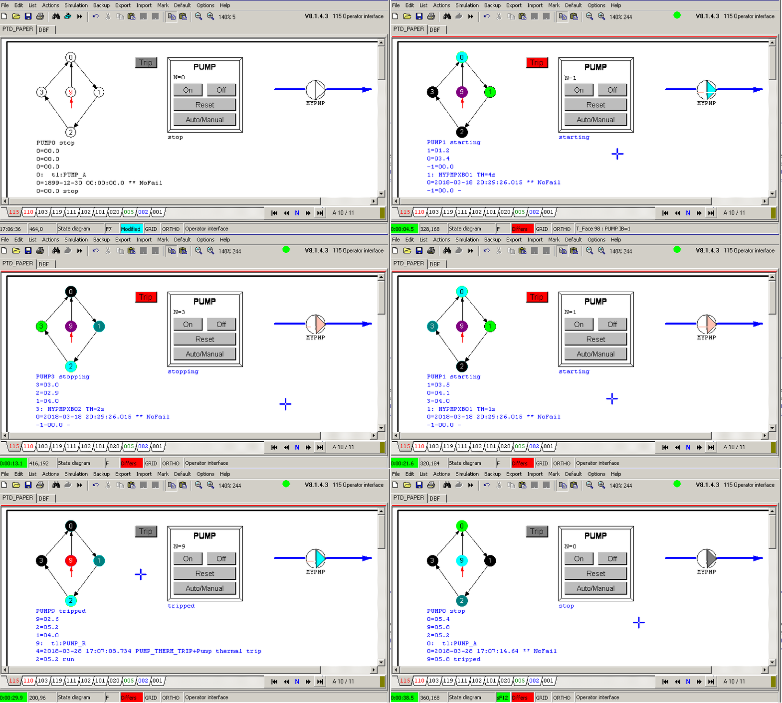
The animation is showing the pump on the right. A skin colored line is showing 0% to 100% active, the MYPMPPOS variable from 0.0 thru 1.0. The intermediate position is blinking. Grey indicates OFF and green is ON.
Under the STD diagram are seven lines of text:
- Shows the active STD Boolean with description
- Shows the active STD number and the elapsed time
- Shows the previous active STD number and its duration
- Shows the previous previous active STD number and its duration
- Shows the active STD number and an enummeration of all leaving transition Booleans.
Showing the remaining time to the next timing parameter. - Shows the current First Failure number, the Trip Boolean and its description and the clock time of activation.
- Shows the active STD state and its elapsed time just befor entering the trip state.
It takes only 5 Integers, 4 Reals and a single Boolean to communicate with the operator screen for a full sized PTD.
By using the three Integers for the active and both previous STD state numbers, the color of each state can be determined. It is black if the state to be drawn does not correspond with these numbers.
The First Failure needs two Integers, the First failure number and the last actual state number at the moment of FF changing a value.
The Reals are needed for the elapsed times or the time stamp.
The single Boolean indicates that the active state has an elapsed time above the TH parameter. This state must blink.
In case of an error, the first failure is telling the story: he was the trip reason. By denoting the clock time the event is fully described. Within the diagram you can see by the colored trace were the failure started. But if the STD has to make some steps to deal with the trip situation, the last actual state and its elapsed time are remembered to be sure.
This elapsed time of the pre-trip state is important information. If it was half an hour, some process problem occured, like too hot. If it was just 0.1 second or a very short time, it is saying that the condition was already True, but out of context. Very important for the technician to repair ir, or for the operator to react upon.
As you can see: only a few numbers and some relevant text to read after a trip and the operator knows what to do. No searching in huge lists, just reading the single first failed trip.


