
PTD pump example
|
|


Example of creating a PTD.
Imagine a pump. It is a common piece of equipment and we are going to privide the control for it using the PTD.
The first task is to realize that we have some inputs, want to take a decision, and create an output.
If (and only if) we are using these elements in a defined sequence, the proper order, we can assure that every cycle of our computer is performing what we want. We must avoid a sloppy sequence, because it will take multiple cycles and we are loosing the ability to prove the correctness of our control. At least I do not understand how to deal with inputs from today and some sloppy status information of the day befor yesterday or worse to create a solid, meaningfull, output.
The PTD is about administrating the status of a process and using the newest inputs to update that status to be sure that is reflects the actual situation and create the output solely based on that actual status. No inputs are allowed to be combinatorically connected to the outputs, because inputs can fail. Outputs must be reliable and predictable depend on the actual status of the STD only. The input failures are dealt with by using the timing of the PTD.
Input section. Page 101.
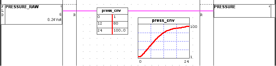
Analogue input.
From left to right you notice the elements I prefer in dealing with an analogue input:
- Input itself. Notice how the LOC field indicates its origin: "FLD"=Field. Some cable is assumed.
The name is intentionally postfixed with "_RAW". See remark at point 3).
Note the "6" is reflecting the WRD value. That raw value is used as the initial value during simulation. I like to be prepared, so that detail is entered by me directly after creating the input.
Note that the IN symbol has an increased height. It shows the range information for the settings of this project. - Conversion to engineering units. The raw input could be 0 thru 4095, or 4096 thru 20479 to reflect the 4 thru 20 mA, or whatever value your PLC input card is providing. In my example some 0 thru 24 Volt signal is indicated. Maybe you need to use a correction curve as well, or implement some calibration result.
The Y=f(X) or Y=g(X) symbols are doing all of that, including the clamping.
The conversion symbol is holding the name "press_cnv", so that the Graph symbol can refer to that name and present it properly.
The result is a functional value, always in the range the engineer expects, and always in the units that makes sense for the process.
If for some reason a new measurement is connected, or the calibration process is renewed, this should be the only location to alter the software. The remaining program must rely on the result of this page. It could be on many places, so it is dealt with at the source of the information to convert it properly. - Functional measurement is given its name, here "PRESSURE", for whatever use in the control.
Boolean input. Also Page 101.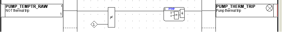
Logical input for an alarm or trip.
From left to right you notice the elements I prefer in dealing with an Boolean input:
- The raw input itself. See 1) of the analogue input.
Because I wrote the description, it corresponds with the True of the signal. Very often it is said "Implicitely you know that." But the signal I am going to use in the program must be functional. Like the conversion to engineering units. - The conversion to documented True.
Many so called "safe wired" inputs are reversed. A emergency shutdown signal is implemented as "NO ESD PRESSED" and is always True unless the button is pressed. I dislike those documented signals. When dealing with thousands of inputs and some of them are safe wired, I respect the electrical side of it, but I want in the documentation only positive descriptions. If you read a description, it must reflect the signal being True. And for better understanding it is forbidden to use negates! (That is for lawyers only, pretending to indicate truth better, but no ...)
Here the Xor symbol is used in combination with the True symbol. I like to implement inverting a signal using these two symbols over the NOT symbol, because it is now easy to undo. By experiencing a project with almost a thousands alarms and trips and an I/O list containing information with a substantial part being wrongly documented (read "inverted"), I was forced to create this Boolean section for getting the documentation in a proper state for the rest of my program. - For alarms and trips only: Use the T_Or symbol to add the proper process context.
In my view an alarm is not the status of the measurement, but always restricted to a certain process context.
Therefor every alarm is associated with a PTD. If you need the same alarm in another PTD as well, just make a parallel branch with another T_or. - The alarm, trip or normal Boolean measurement, is given a functional name and a description which reflects the True status of the signal.
I like to add "_ALM" or "_TRIP" to the name for clarity.
A lot of DCS systems provide an alarm list. I hate that list, because in times of emergency the operator must react within seconds. He does not have the luxury of walking through a list of hundreds of alarm notifications to decide. I deal with the alarm at the source by associating the relevant and sensitive process states. In my case the horn will not sound and the screens are not flashing red if it was not worth alerting. - PUMP_FF. If zero, the catch of a First Failure is active. It is waiting for an input on the left to become True.
If that happens, the clock time is used to note the event and PUMP_FF contains the number as seen at the connection.
In case of the FFailN his offset number is added to avoid duplications in numbers. - PUMP_FF_T holds the time of the last event.
- PUMP_FF_N holds the number of the previous event.
- PUMP_FF_TN holds the clock time of the previous event.
Alarm section. Page 102.
Alarm settings for analogue measurements.
From left to right you see how I want to address the alarm settings.
But first the remark about the sequence. After the input section we have clean functional analogue measurement, like PRESSURE. Logically this section is the successor of the input section. In my example the next page: 102.
A lot of DCS systems have intelligent I/O cards. Often with these alarm settings on board and even with creating time stamps at transition moments for logging purposes. I dislike the abundant amount of information and like to filter it myself.
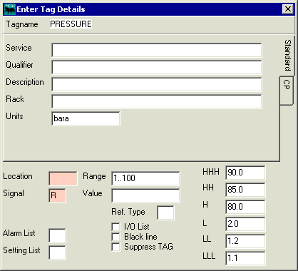
TagDetails for PRESSURE.
HCADwin can hold as many settings as you like for each measurement, but here the six normal settings are part of the DBF record: LLL, LL, L, H, HH and HHH are column names and filled.
Using the Test symbol would be a logical approach, but the TAGtst symbol offers the connection with the DBF by referring to a column name.
The above logic page is showing how all six settings are used to create the six Boolean variables. I like to add the column name to the measurement name to get meaningfull names.
Note that the real alarm or trip variables are provided with the T_Or symbol to indicate the process context. All about preventing alarms to alert the operator if it has no significance.

TagDetails for PRESSURE_HHH.
Note that the corresponding OUT symbol is holding an indication for a light (circle with crossed lines), because it is an alarm. The red line on the right indicates that also. The DBF is holding the Alarm level 3 for this variable, as shown above.
To deal with hysteresis or any other peculiar behavior, you could use a Delay symbol befor the TAGtst, or a T->0 symbol after it. Just a matter of taste or whatever is required.
Nomenclature (name giving) becomes very important when dealing with huge projects. In spite of what you may think, the larger the firm the worse they perform. I have seen systems with over 60% violations of proper name giving, like KKS. This is a major cause for human error. Like the lack of sequence structure in the implementation is giving unwanted memories and weird behavior at the very moments of thruth when an operator is given only a short period to react.
Please keep the structures, names and documentation in a simple fashion. Readable and reliable.
First failure section. Page 103.

First Failure for PUMP PTD.
The logical position in the sequence for the ultimate PTD handling of trips is after making the alarms and befor the STD itself.
The FFail symbol is used here, but in case of multiple trip states you must define a FFailN symbol also.
Again a notation issue which is important: the FFail (FFailN) name must be the STD name with "_FF" at the end. Secondly it is good practice to use the trip Boolean name by using the STD name with "_TRIP+state number".
This First Failure handling is implemented as an Integer variable with the name PUMP_FF here. Let us explain what variables are involved:
The second reason to forbid complex logic here, is the automatic "Cause and Effect" to show all trips, its context and effects.
Functionally this is a simple and elegant solution to integrate the fail safe requirements with the normal logic control. By defining trip states in the STD and associating both the trip conditions and outputs to the equipment energized, no weird additional logic is needed.
And it remains readable and reliable!
I think that the PRESSURE_LLL and PRESSURE_HHH are well understood. If the pressure is outside safe boundaries, AND within a certain process context, the diagram should enter a trip state (here PUMP9).
The PUMP_THERM_TRIP is just the same, but based on a Boolean measurement.
The PUMP_ESD is a result of the T_Adm symbol which is created later. Any state can hold an "Emergency time", the "TE". If the duration of the state timer elapses beyond that parameter, this Boolean becomes True. States which can last forever are given TE=0, to indicate infinity.
STD section. Page 110.
Press this button to see how the STD is created.
Press the other buttons on the upper left side of the pages to see page 111 for associating the equipment energized output and page 119 for simulating that equipment.
After creating the full sequence of pages in the intended order, the STD is finished by giving the transition Boolean the proper names and attributes. All states are given proper timing parameters and the project is compiled and simulated.